The RHODaS Project aims to make significant advancements in efficiency and thermal performance that will allow further driving range extension, faster charging and easier thermal management of the whole powertrain, as well as possible improvement in cabin-heating and defrosting in winter.

Enhancements to the thermal performance of the powertrains and the extension of the truck driving range by 10% aims to be achieved by exploiting the wide frequency range of the wide band gap materials integrated in the powertrains. Hybrid switches will increase the temperature of operation. A more effective hybrid thermal management system combining micro liquid-cooling and air-cooling systems to mitigate negative effects of high current on health and ageing of the materials and components will also be implemented.
A new report by Aarhus University offers a detailed overview of thermal management system strategies, modeling, and simulation within the RHODaS project. Initially, it focuses on outlining the thermal interface between inverters and cooling systems, examining estimated junction temperatures, and evaluating the potential impacts of design choices on equivalent thermal resistance.

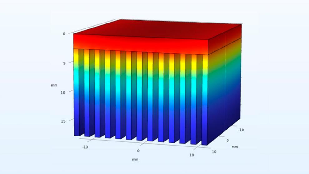
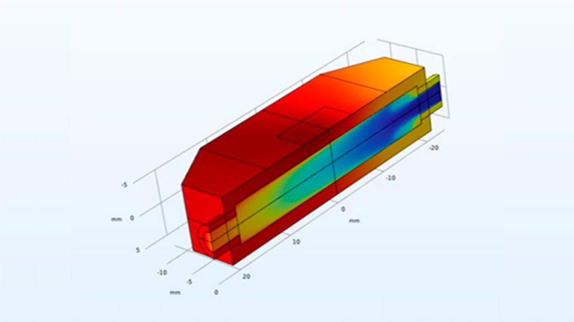
The document also delves into advanced 3D thermal and power loss modeling, utilising Finite Element Analysis, with a significant emphasis on the role played by COMSOL Multiphysics in heatsink design. Essential simulations cover aspects like liquid-cooled heatsink design and sensitivity studies. Notable contributions such as the introduction of the thermal equivalent circuit model, the RHODaS Thermal Management System Toolbox, and the strategic decision to design six heatsinks for a high-power converter are also covered in the report.
The conclusion addresses the need for advancements in temperature monitoring, proposing sensor networks, and outlining strategies for precise readings to enhance the overall effectiveness of the thermal management approach within the RHODaS project.
Download and read the full report here RHODaS D3.1 Thermal Management
Image 1: The results of temperature distribution in the designed air cooled heatsink
Image 2: The result of temperature distribution in the liquid-cooled heatsink